Spherical True Position Tolerance Calculator
Tolerances, Engineering Design & Limits & Fits
(This calculator requires a java - enabled browser)
This calculator calculates position tolerances utilizing principles and concepts within ASME Y14.5-2009 and ASME Y14.5M - 1994, Geometric Dimensioning and Tolerancing (GD&T).
Open Spherical True Position Calculator
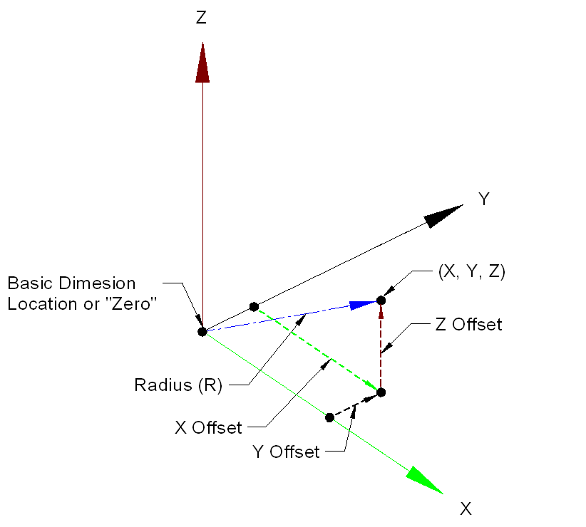
This calculator will convert coordinate measurements to position tolerances. Three (3) inputs are required, See the application illustration at bottom of page.
The following are definitions for the elements:
X Offset - This is the difference between the basic dimension (Drawing) and the actual measurement of the produced part in the X axis direction.
Y Offset - This is the difference between the basic dimension (Drawing) and the actual measurement of the produced part in the Y axis direction.
Z Offset - This is the difference between the basic dimension (Drawing) and the actual measurement of the produced part in the Z axis direction.
Calculated (ACTUAL) Radius True Position - The calculated radius offset
see Spherical True Position Calculator .
Calculated (ACTUAL) Spherical True Position - The calculated spherical positional tolerance diameter zone (2 x R).

Related Resources:
- True Position GD&T Tolerance Calculator
- Tolerance Calculator Floating Fastener Condition
- Tolerance Calculator Fixed Fastener Condition
- Tolerance Calculator Projected Tolerance Zone
- Tolerance Calculator 2 Mating Features @ MMC
- Tolerance Calculator 3 Mating Features @MMC
- Tolerance Calculator - True Position
- Tolerance Calculator - Spherical True Position
- Hole / Feature Pattern Plot
- GD&T Geometric Dimensioning Tolerancing Basics Training
- GD&T Geometric Dimensioning Tolerancing Intermediate Training
- GDT ASME Y14.5-2009 Applications Training
- G&T Geometric Tolerancing ISO 1101 Training
- Online GD&T Fundamentals Training