Related Resources: civil engineering

Load Bearing Walls Review Design , Equation, Wall Stud Spacing Table

 
Load Bearing Walls Review, Equation and Wall Stud Spacing Design Table
 
A load-bearing wall (or bearing wall) is a wall that bears a load resting upon it by conducting its weight to a foundation structure. The materials most often used to construct load-bearing walls in large buildings are concrete, block, or brick.
 
By contrast, a curtain wall provides no significant structural support beyond what is necessary to bear its own materials or conduct such loads to a load-bearing wall.
 
Depending on the type of building and the number of stories, load-bearing walls are gauged to the appropriate thickness to carry the weight above them. Without doing so, it is possible that an outer wall could become unstable if the load exceeds the strength of the material used, potentially leading to the collapse of the structure.
 
In residential housing, load-bearing walls are most common in the light construction method known as "platform framing", and each load-bearing wall sits on a wall sill plate which is mated to the lowest base plate. The sills are bolted to the masonry or concrete foundation.
 
The top plate or ceiling plate is the top of the wall, which sits just below the platform of the next floor (at the ceiling). The base plate or floor plate is the bottom attachment point for the wall studs. Using a top plate and a bottom plate, a wall can be constructed while it lies on its side, allowing for end-nailing of the studs between two plates, and then the finished wall can be tipped up vertically into place atop the wall sill; this not only improves accuracy and shortens construction time, but also produces a stronger wall.
 
Supertall skyscrapers - Due to the immense weight of skyscrapers, the base and walls of the lower floors must be incredibly strong. Pilings are used to anchor the building to the bedrock underground. For example, the Burj Khalifa, the world's tallest building as well as the world's tallest structure, uses specially treated and mixed reinforced concrete. Over 45,000 cubic metres (59,000 cu yd) of concrete, weighing more than 110,000 t (120,000 short tons) were used to construct the concrete and steel foundation, which features 192 piles, with each pile being 1.5 m diameter x 43 m long (4.9 ft x 141 ft) and buried more than 50 m (160 ft) deep.
 
These are subject to axial compression loads in addition to their own weight and, where there is eccentricity of load or lateral loads, to flexure. Load-bearing walls may be designed in a manner similar to that for columns but including the design requirements for non-load-bearing walls.
 
As an alternative, load-bearing walls may be designed by an empirical procedure given in the ACI
 
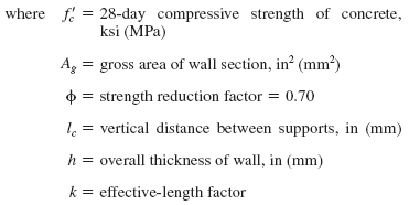
Code when the eccentricity of the resulting compressive load is equal to or less than one-sixth the thickness of the wall. Load-bearing walls designed by either method should meet the minimum reinforcing requirements for non-loadbearing walls. In the empirical method the axial capacity, kip (kN), of the wall is:


For a wall supporting a concentrated load, the length of wall effective for the support of that concentrated load should be taken as the smaller of the distance center to center between loads and the bearing width plus 4h.

Recommended maximum allowable length of wood wall studs exposed to wind speeds of 100 MPH or less in seisnic design categoreis.

 
Height

On Center Spacer (Inches)

24
16
12

8

Supporting a Roof Only
>10
2x4
2x4
2x4
2x4
12
2x6
2x4
2x4
2x4
14
2x6
2x6
2x6
2x4
16
2x6
2x6
2x6
2x4
18
NA a
2x6
2x6
2x6
20
NA a
NA a
2x6
2x6
24
NA a
NA a
NA a
2x6
Supporting One Floor and a Roof
>10
2x6
2x4
2x4
2x4
12
2x6
2x6
2x6
2x4
14
2x6
2x6
2x6
2x6
16
NA a
2x6
2x6
2x6
18
NA a
NA a
2x6
2x6
20
NA a
NA a
2x6
2x6
24
NA a
NA a
NA a
2x6
Supporting Two Floors and a Roof
>10
2x6
2x6
2x4
2x4
12
2x6
2x6
2x6
2x6
14
2x6
2x6
2x6
2x6
16
NA a
NA a
2x6
2x6
18
NA a
NA a
NA a
2x6
20
NA a
NA a
NA a
NA a
24
NA a
NA a
NA a
NA a

Notes:

a. Engineering design analysis required for this application
b. Application of this chart assumes Snow Load not exceeding 25 psf, fb 1not less than 1310 psi determined by multiplying AF&PA NDS tabular base design value by repetitive use factor, and by the size factor for species except southern pine. E not less than 1.6 x 10⁶ and tributary dimensions for floors and roofs not exceeding 6 ft., maximum span for floors and roof exceeding 12 ft., eaves not greater than 2 ft. in dimension and sheathing.
c. Utility, standard, stud and No. 3 grade lumber of any species not permitted
d. Check with local codes - as the above design criterion does not supercede such.

Related: