Diesel Engine Camshaft, Timing Gears and Valve Mechanism
Power Transmission and Technology Menu
Diesel Engine Camshaft, Timing Gears and Valve Mechanism
In order for a diesel engine to operate, all of its components must perform their functions at very precise intervals in relation to the motion of the piston. To accomplish this, a component called a camshaft is used. Figure 9 illustrates a camshaft and camshaft drive gear. Major Components of a Diesel Engine illustrate the location of a camshaft in a large overhead cam diesel engine.
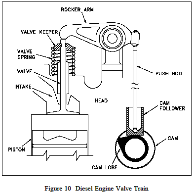
A camshaft is a long bar with egg-shaped eccentric lobes, one lobe for each valve and fuel injector. Each lobe has a follower as shown on Figure 10. As the camshaft is rotated, the follower is forced up and down as it follows the profile of the cam lobe. The followers are connected to the engine's valves and fuel injectors through various types of linkages called pushrods and rocker arms. The pushrods and rocker arms transfer the reciprocating motion generated by the cam shaft lobes to the valves and injectors, opening and closing them as needed. The valves are maintained closed by springs.

As the valve is opened by the camshaft, it compresses the valve spring. The energy stored in the valve spring is then used to close the valve as the camshaft lobe rotates out from under the follower. Because an engine experiences fairly large changes in temperature (e.g., ambient to a normal running temperature of about 190F), its components must be designed to allow for thermal expansion. Therefore, the valves, valve pushrods, and rocker arms must have some method of allowing for the expansion. This is accomplished by the use of valve lash. Valve lash is the term given to the "slop" or "give" in the valve train before the cam actually starts to open the valve.
The camshaft is driven by the engine's crank shaft through a series of gears called idler gears and timing gears. The gears allow the rotation of the camshaft to correspond or be in time with, the rotation of the crank shaft and thereby allows the valve opening, valve closing, and injection of fuel to be timed to occur at precise intervals in the piston's travel. To increase the flexibility in timing the valve opening, valve closing, and injection of fuel, and to increase power or to reduce cost, an engine may have one or more camshafts. Typically, in a medium to large V-type engine, each bank will have one or more camshafts per head. In the larger engines, the intake valves, exhaust valves, and fuel injectors may share a common camshaft or have independent camshafts.
Depending on the type and make of the engine, the location of the camshaft or shafts varies. The cam shaft (s) in an in-line engine is usually found either in the head of the engine or in the top of the block running down one side of the cylinder bank. Figure 10 provides an example of an engine with the camshaft located on the side of the engine. Figure 3, (Major Components of Diesel Engine) provides an example of an overhead cam arrangement as on a V-type engine. On small or mid-sized V-type engines, the camshaft is usually located in the block at the center of the "V" between the two banks of cylinders. In larger or multi-cam shafted V type engines, the camshafts are usually located in the heads.