AC Alternator Types Alernating Current Review
Industrial Electric Motors and Generators Menu
Electric Generators Suppliers
AC Alternator Types Review
Alternators are single-phase or polyphase. Variations include three-phase alternators used as single-phase units by insulating and not using one phase lead. Since the lead is unused, it is not brought out to a terminal. The power rating is reduced from that of the three-phase unit as limited by the amount of current carried by a coil. An alternator designed only for single-phase operation usually does not have coils in all of the armature slots because end coils contribute little to the output voltage and increase the coil impedance in the same proportion as any other coil.
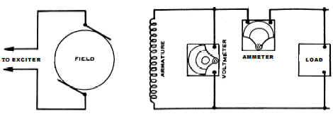
Single-phase alternators are usually used in smaller systems (limited to 25kW or less) and produce AC power at utilization voltages. Terminal voltage is usually 120 volts. The electric load is connected across the terminals with protective fuses. One voltmeter and one ammeter measure the output in volts and amperes, respectively The two-wire alternator has two power terminals, one for each end of the armature coil.
Two-wire, single-phase alternator
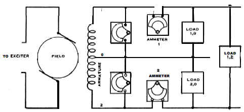
The three-wire, single-phase alternator has three power terminals; one from each end of the armature coil and one from the midpoint . Terminal voltage is usually 120 volts from the midpoint to either end of the armature coil and 240 volts between the two ends. The load is connected between the two outside wires or between either outside wire and neutral, depending upon the voltage required by the load. Assuming alternator voltage to be 120/240 volts, load 1,0 and load 2,0 would consist of 120-volt lamps and 120-volt single phase power equipment. Load 1,2 would consist of 240-volt power equipment. Two voltmeters and two ammeters (or equivalent) are required to determine the load in kilovolt amperes (kVA).
Three-wire, single-phase alternator
Polyphase alternators are two, three, or six phases. Two-phase power is used in only a few localities. Six-phase is primarily used for operation of rotary converters or large rectifiers. Three-phase alternators are the most widely used for power production. Polyphase alternators have capacities from 3 kW to 250,000 kW and voltage from 110 V to
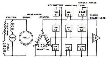
13,800 V. Two general types of three-phases alternator windings are the delta winding used in three wire, three-phase alternators, and the star or wye winding used in four-wire, three-phase types. Three-wire, three-phase alternators have three sets of single-phase windings spaced 120 electrical degrees apart around the armature. One electrical degree is equivalent to one degree of arc in a two pole machine, 0.50 degree of arc in a four-pole machine, 0.33 degree of arc in a six-pole machine, and so on. The three single-phase windings are connected in series to form the delta connection, and
the terminals are connected to the junction point of each pair of armature coils (see illustration below - Three-wire, three-phase alternator). The total current in a delta-connected circuit is always equal to the vector sum of currents in two-phase windings. The instantaneous current flows out to the load through two windings and returns from the load through the third winding. Since the coils are similar physically and electrically, equal voltages are generated and applied to the terminals. Due to spacing of the coils about the armature, the maximum voltage between the pairs of terminals does not occur simultaneously.
Three-wire, three-phase alternator
The characteristics of three- wire, three-phase (or delta) alternators are:
- The amount of current through the alternator terminals is the algebraic sum of current through the alternator coils.
- The currents are not equal in magnitude or time.
- Connection between coils can be made either inside or outside the generator.
- In a 60-Hertz machine, each coil experiences maximum instantaneous voltage, first positive and then negative, 120 times each second. Disregarding voltage direction, the maximum instantaneous voltages occur on successive coils 0.003 seconds apart. Due to time differences between the voltages and resulting currents, the amount of current through the alternator terminals and the amount through the alternator coils are not equal in magnitude or time. The current through the alternator is 73 percent greater than through the coils. Coil and terminal voltages are the same magnitude. Three voltmeters and three ammeters (or equivalent) are required to measure the load on the alternator. The average value of the three currents times the average value of the three voltages plus 73 percent gives a close approximation of the alternator load in kilovolt-amperes. Two single-phase or one two element polyphase kilowatt-hour meter is required to measure the alternator output in kilowatt-hours.
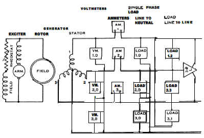
The four-wire, three-phase alternator has three sets of armature coils spaced 120 electrical degrees apart about the armature, the same as the three-wire, three-phase alternator. One end of each of the three coils is connected to a common terminal (neutral). The other end of each coil is connected to separate terminals (phase terminals). Thus, the four-wire alternator has four terminals which connect to the three-phase conductors and the neutral of the power-plant bus. When each end of each coil is brought out to separate terminals, the connections between coils are made outside of the alternator, enabling installation of a more comprehensive protective relaying system.
Four-wire, three-phase alternator
The four-wire, three-phase alternator can be connected to a transformer instead of the power plant bus by using a wye-wye transformation. Irregular (double or triple) harmonics, which may be produced, can be suppressed by using a core-type transformer. A third or tertiary winding with a delta connection may also be used as a suppressor. A wye-delta transformer may be used if the power plant bus is three wire and the alternator is four wire wye connected.
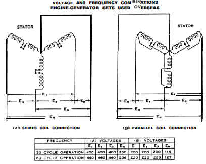
Four-wire three-phase, dual voltage and frequency alternators are also used. These are supplied in sizes from 15 to 1500 kW, 127-220 volts, three-phase, 60 Hertz, or 230-400 volts, three phase, 50 Hertz. Dual stator coils are used on each phase. Coil ends are brought out to a terminal board for making connections. Voltage and frequency combinations are shown in below (Dual voltage and Frequency).
Dual voltage and Frequency
Most parts of the world have standardized on either 50 or 60 Hertz alternating current power. Sixty Hertz power is commonly used in the United States. Fifty Hertz power is used in many countries outside the United States. The ratio be-teen the 60-50 Hertz frequencies is 6:5. Electrical energy received at one frequency can be converted to a different frequency by using a frequency changer. If a large power requirement exists, it may be more economical to use a special alternator to produce power at the desired frequency.
The applicable equation is:
V = K θ N f
Where:
V = generated voltage
K = constant value number (speed)
θ = phase/phase angle
N = number of turns
f = line frequency
The generated voltage is proportional to the strength of the magnetic field, phase, and number of turns in series between terminals and the speed.
References: “Joint Departments of the Army and the Navy, Operation Maintenance and Repair of Auxiliary Generators, 26 August 1996”
Link to this Webpage:
© Copyright 2000 -
2024, by Engineers Edge, LLC
www.engineersedge.com
All rights reserved
Disclaimer |
Feedback
Advertising
| Contact
