Related Resources: mechanics machines
Shrink Fit of Links or Anchors of Length Equations
Engineering Analysis
Strength and Mechanics of Materials Menu
Shrink Fit of Links or Anchors of Length Equations
Shrink-fit connections utilizing a link or anchor are widely used in machine design and construction.
The average compression in the part of rim affected according to C. D. Albert
Eq. 1
σc = F / ( Ab Ar )0.5
The tensile stress in link formula
Eq. 2
σt = ( Lf - Lo ) / Lo
The total load on link formula
Eq. 3
F = [ ( Lf - Lo ) E A ] / Lo
The compressive stress in rim formula
Eq. 4
σc = [ ( Lf - Lo ) / Lo ] ( E A ) / ( Ab Ar )0.5
The original length of link
Eq. 5
Lo = L / [ 1 + ( 1 + ( E A ) / ( Ab Ar )0.5 ) ( σr / E ) ]
The necessary linear interference δ for shrink anchors
Eq. 6
δ = σd l / L
The force exerted by an anchor
Eq. 7
F = a b σd
Eq. 8
b / a = 2 to 3
Eq. 9
σd design stress based on a reliability factor of 1.25

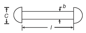
Figure 1 Shrink links or anchors
where
F = load , kN (lbf)
E = modulus of elasticity or Young’s modulus, Pa [psi (lb/in2)]
A = cross section area, m2, in2
Ab = area bearing surface rim, m2, in2
Ar = area rim, m2, in2
Lo = original length, m (in)
Lf = final length, m (in)
l = effective length of anchor, m (in)
ρ = mass density, kg/m3 (lbm/in3)
v = Poisson's ratio
u = displacement, m (in)
Related:
- Preferred Force Shrink Fits Chart ANSI B4.1 Calculator
- Bushing and Plain Bearings Press or Shrink Fit Design and Application
- Shrink Thermal Fit Review
- Interference Pressure Mechanical Tolerances Variability Equations and Calculator
- Cylinder Feature Press Fit Design Equations
Source:
Machine Design Handbook 2nd Edition, 2001
Prof. Dr. K. Lingaiah
Former Principal, Professor and Head, Department of Mechanical Engineering
University Visvesvaraya College of Engineering, Bangalore University, Bangalore