Wheatstone Bridge Circuit Equations and Derivation
Electronics, Instrumentation & Electrical Database
Wheatstone Bridge Circuit Equations and Derivation
Related Resources:
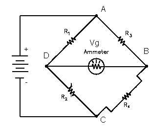
The illustration below shows a basic bridge circuit which consists of three known resistance's R1, R2, and R3 (variable), an unknown variable resistor RX (RTD), a source of voltage, and a sensitive ammeter.

Resistors R1 and R3 are the ratio arms of the bridge. They ratio the two variable resistance'sfor current flow through the ammeter. R2 is a variable resistor known as the standard arm that is adjusted to match the unknown resistor. The sensing ammeter visually displays the current that is flowing through the bridge circuit. Analysis of the circuit shows that when R2 is adjusted so that the ammeter reads zero current, the resistance of both arms of the bridge circuit is the same. The equation below shows the relationship of the resistance between the two arms of the bridge.

Since the values of R1, R2, and R3 are known values, the only unknownis Rx. The value of Rx can be calculatedfor the bridge during an ammeter zero current condition. Knowing this resistance value provides a baseline point for calibration of the instrument attached to the bridge circuit. The unknown resistance, Rx, is given by:.

History:
The Wheatstone bridge was invented by Samuel Hunter Christie in 1833 and improved and popularized by Sir Charles Wheatstone in 1843. It is used to measure an unknown electrical resistance by balancing two legs of a bridge circuit, one leg of which includes the unknown component. Its operation is similar to the original potentiometer.
Derivation:
First, Kirchhoff's first rule is used to find the currents in junctions B and D:
![]()
![]()
Then, Kirchhoff's second rule is used for finding the voltage in the loops ABD and BCD:
![]()
![]()
The bridge is balanced and Ig = 0, so the second set of equations can be rewritten as:
![]()
![]()
Then, the equations are divided and rearranged, giving:
![]()
From the first rule, I3 = Ix and I1 = I2. The desired value of Rx is now known to be given as:
![]()
If all four resistor values and the supply voltage (VS) are known, and the resistance of the galvanometer is high enough that Ig is negligible, the voltage across the bridge (VG) can be found by working out the voltage from each potential divider and subtracting one from the other. The equation for this is:
![]()
This can be simplified to:
![]()
where VG is the voltage of node B relative to node D.