Inductance Type Transducer Review
Electronics, Instrumentation & Electrical Database
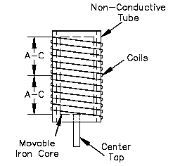
The inductance-type transducer consists of three parts: a coil, a movable magnetic core, and a pressure sensing element. The element is attached to the core, and, as pressure varies, the element causes the core to move inside the coil. An AC voltage is applied to the coil, and, as the core moves, the inductance of the coil changes. The current through the coil will increase as the inductance decreases. For increased sensitivity, the coil can be separated into two coils by utilizing a center tap, as shown in Figure A-1. As the core moves within the coils, the inductance of one coil will increase, while the other will decrease.

Figure A-1
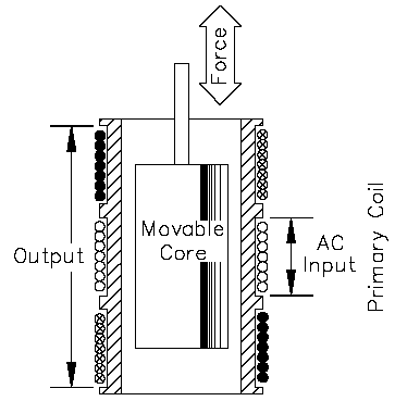
Another type of inductance transducer, illustrated in Figure A-2, utilizes two coils wound on a single tube and is commonly referred to as a Differential Transformer.

Figure A-2
The primary coil is wound around the center of the tube. The secondary coil is divided with one half wound around each end of the tube. Each end is wound in the opposite direction, which causes the voltages induced to oppose one another. A core, positioned by a pressure element, is movable within the tube. When the core is in the lower position, the lower half of the secondary coil provides the output. When the core is in the upper position, the upper half of the secondary coil provides the output. The magnitude and direction of the output depends on the amount the core is displaced from its center position. When the core is in the mid-position, there is no secondary output.