Simple Ohm Meter Review
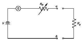
The ohm meter is an instrument used to determine resistance, such as that created by a resistor. A simple ohm meter consists of a battery, a meter movement calibrated in ohms, and a variable resistor.
Ohm meters are connected to a component which is removed from the circuit as illustrated below. The reason for removing the component is that measurement of current through the component determines the resistance. If the component remains in the circuit, and a parallel path exists in the circuit, the current will flow in the path of least resistance and give an erroneous reading.
Ro, shown below, is an adjustable resistor whose purpose is to zero the ohm meter and correct for battery aging. It is also a current-limiting resistor which includes the meter resistance Rm. Zeroing the ohm meter is accomplished by shorting the ohm meter terminals ab and adjusting Ro to give full-scale deflection.

The equation below is the mathematical representation for determining full-scale deflection meter current
Im = V / Ro
When the unknown resistance Rx is connected across the ohm meter terminals, the current is measured by calculating the total series resistance and applying the equation above. The equation below is the mathematical representation of this concept.
I = V / ( Ro + Rx )