Related Resources: instrumentation
Coaxial Cable, Connectors Assemblies Review
Coaxial cable differs from other shielded cable used for carrying lower-frequency signals, such as audio signals, in that the dimensions of the cable are controlled to give a precise, constant conductor spacing, which is needed for it to function efficiently as a radio frequency transmission line. Coaxial cable, or coax, is constructed with an inner conductor surrounded by a flexible, tubular insulating layer, surrounded by a tubular conducting shield.
 |
|
Air-Dielectric Coax |
Common applications of coaxial cable: Video and CATV distribution, RF and microwave transmission, and computer and instrumentation data connections.
The characteristic impedance of the cable (Z0) is determined by the dielectric constant of the inner insulator and the radii of the inner and outer conductors. A controlled cable characteristic impedance is important because the source and load impedance should be matched to ensure maximum power transfer and minimum Standing Wave Ratio. Other important properties of coaxial cable include attenuation as a function of frequency, voltage handling capability, and shield quality.
Construction:
Coaxial cable design choices affect physical size, frequency performance, attenuation, power handling capabilities, flexibility, strength, and cost. The inner conductor might be solid or stranded; stranded is more flexible. To get better high-frequency performance, the inner conductor may be silver-plated. Sometimes copper-plated iron wire is used as an inner conductor.
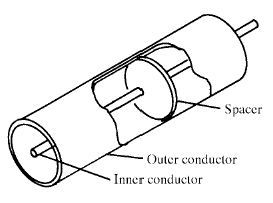
The insulator surrounding the inner conductor may be solid plastic, a foam plastic, or air with spacers supporting the inner wire. The properties of dielectric control some electrical properties of the cable. A common choice is a solid polyethylene (PE) insulator, used in lower-loss cables. Solid Teflon (PTFE) is also used as an insulator. Some coaxial lines use air (or some other gas) and have spacers to keep the inner conductor from touching the shield.
Many conventional coaxial cables use braided copper wire forming the shield. This allows the cable to be flexible, but it also means there are gaps in the shield layer, and the inner dimension of the shield varies slightly because the braid cannot be flat. Sometimes the braid is silver-plated. For better shield performance, some cables have a double-layer shield. [4] The shield might be just two braids, but it is more common now to have a thin foil shield covered by a wire braid. Some cables may invest in more than two shield layers, such as "quad-shield," which uses four alternating layers of foil and braid. Other shield designs sacrifice flexibility for better performance; some shields are a solid metal tube. Those cables cannot take sharp bends, as the shield will kink, causing losses in the cable.
For high-power radio-frequency transmission up to about 1 GHz, coaxial cable with a solid copper outer conductor is available in sizes of 0.25 inch upward. The outer conductor is rippled like a bellows to permit flexibility and the inner conductor is held in position by a plastic spiral to approximate an air dielectric.
Coaxial cables require an internal structure of an insulating (dielectric) material to maintain the spacing between the center conductor and shield. The dielectric losses increase in this order: Ideal dielectric (no loss), vacuum, air, Polytetrafluoroethylene (PTFE), polyethylene foam, and solid polyethylene. A low relative permittivity allows for higher-frequency usage. An inhomogeneous dielectric needs to be compensated by a non-circular conductor to avoid current hot-spots.
Most cables have a solid dielectric; others have a foam dielectric that contains as much air as possible to reduce the losses. Foam coax will have about 15% less attenuation but can absorb moisture�especially at its many surfaces in humid environments, increasing the loss. Supports shaped like stars or spokes are even better but more expensive. In some low-loss coaxial cables such as an RG-62 type, the inner conductor is supported by a spiral strand of polyethylene, so that an air space exists between most of the conductor and the inside of the jacket. The lower dielectric constant of air allows for a greater inner diameter at the same impedance and a greater outer diameter at the same cutoff frequency, lowering ohmic losses. Inner conductors are sometimes silver-plated to smooth the surface and reduce losses due to skin effect. A rough surface prolongs the path for the current and concentrates the current at peaks and, thus, increases ohmic losses.
The insulating jacket can be made from many materials. A common choice is PVC, but some applications may require fire-resistant materials. Outdoor applications may require the jacket to resist ultraviolet light and oxidation. For internal chassis connections the insulating jacket may be omitted.
Open-wire transmission lines have the property that the electromagnetic wave propagating down the line extends into the space surrounding the parallel wires. These lines have low loss, but also have undesirable characteristics. They cannot be bent, twisted, or otherwise shaped without changing their characteristic impedance, causing reflection of the signal back toward the source. They also cannot be run along or attached to anything conductive, as the extended fields will induce currents in the nearby conductors causing unwanted radiation and detuning of the line. Coaxial lines solve this problem by confining virtually all of the electromagnetic wave to the area inside the cable. Coaxial lines can therefore be bent and moderately twisted without negative effects, and they can be strapped to conductive supports without inducing unwanted currents in them.
In radio-frequency applications up to a few gigahertz, the wave propagates primarily in the transverse electric magnetic (TEM) mode, which means that the electric and magnetic fields are both perpendicular to the direction of propagation. However, above a certain cutoff frequency, transverse electric (TE) and/or transverse magnetic (TM) modes can also propagate, as they do in a waveguide. It is usually undesirable to transmit signals above the cutoff frequency, since it may cause multiple modes with different phase velocities to propagate, interfering with each other. The outer diameter is roughly inversely proportional to the cutoff frequency. A propagating surface-wave mode that does not involve or require the outer shield but only a single central conductor also exists in coax but this mode is effectively suppressed in coax of conventional geometry and common impedance. Electric field lines for this [TM] mode have a longitudinal component and require line lengths of a half-wavelength or longer.
Coaxial cable may be viewed as a type of waveguide. Power is transmitted through the radial electric field and the circumferential magnetic field in the TEM00 transverse mode. This is the dominant mode from zero frequency (DC) to an upper limit determined by the electrical dimensions of the cable.
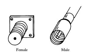
A coaxial connector (male N-type).Main article: RF connector
The ends of coaxial cables usually terminate with connectors. Coaxial connectors are designed to maintain a coaxial form across the connection and have the same well-defined impedance as the attached cable. Connectors are often plated with high-conductivity metals such as silver or gold. Due to the skin effect, the RF signal is only carried by the plating and does not penetrate to the connector body. Although silver oxidizes quickly, the silver oxide that is produced is still conductive. While this may pose a cosmetic issue, it does not degrade performance.
Standards:
Most coaxial cables have a characteristic impedance of either 50, 52, 75, or 93 ohms. The RF industry uses standard type-names for coaxial cables. Thanks to television, RG-6 is the most commonly-used coaxial cable for home use, and the majority of connections outside Europe are by F connectors.
 |
|
coaxial cable
(From left to right: insulating jacket, woven outer conductor, low-loss insulating sleeve, inner conductor.) |
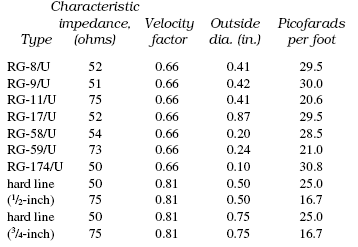
Characteristics of prefabricated coaxial tranmission lines.

