Related Resources: hardware
Parallel Key and Taper Keys Dimensions
Metric ISO Hardware
ANSI Engineering Design Hardware
Parallel Key and Taper Keys Dimensions and Sizes per. ISO 6885, Part 1, 6886 and 6887
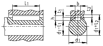
Side fitting square and rectangular keys
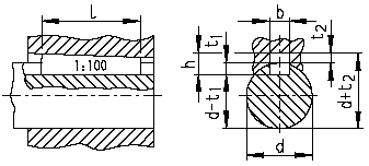
Square and rectangular taper keys
Side fitting square and rectangular keys

Parallel key and keyway acc. to ISO 6885 Part 1
Square and rectangular taper keys

Taper and round-ended sunk key and
keyway acc. to ISO 6886
Dimensions of parallel keys and taper keys
1) The tolerance zone for hub keyway width b for parallel keys with normal fit is ISO JS9 and with close fit ISO P9. The tolerance zone for shaft keyway width b with normal fit is ISO N9 and with close fit ISO P9.
2) Dimension h of the taper key names the largest height of the key, and dimension tz largest depth of the hub keyway. The shaft keyway and hub keyway dimensions according to ISO 6887 - taper keys with gib head - are equal to those in ISO 6886
Dimensions of Parallel Keys and Taper Keys
Diameter d |
Width b |
Height h |
Depth of Keyway in Shaft t1 |
Depth of Keyway in Hub t2 |
Lengths |
|||||
Above |
To |
1) |
2) |
- |
6885/1 |
6886 6887 2) |
I1 6885/1 |
I 6886 |
||
6 |
8 |
2 |
2 |
1.2 |
1.0 |
0.5 |
6 |
20 |
6 |
20 |
8 |
10 |
3 |
3 |
1.8 |
1.4 |
0.9 |
6 |
36 |
8 |
36 |
10 |
12 |
4 |
4 |
2.5 |
1.8 |
1.2 |
8 |
45 |
10 |
45 |
12 |
17 |
5 |
5 |
3 |
2.3 |
1.7 |
10 |
56 |
12 |
56 |
17 |
22 |
6 |
6 |
3.5 |
2.8 |
2.2 |
14 |
70 |
16 |
70 |
22 |
30 |
8 |
7 |
4 |
3.3 |
2.4 |
18 |
90 |
20 |
90 |
30 |
38 |
10 |
8 |
5 |
3.3 |
2.4 |
22 |
110 |
25 |
110 |
38 |
44 |
12 |
8 |
5 |
3.3 |
2.4 |
28 |
140 |
32 |
140 |
44 |
50 |
14 |
9 |
5.5 |
3.8 |
2.9 |
36 |
160 |
40 |
160 |
50 |
58 |
16 |
10 |
6 |
4.3 |
3.4 |
45 |
180 |
45 |
180 |
58 |
65 |
18 |
11 |
7 |
4.4 |
3.4 |
50 |
200 |
50 |
200 |
65 |
75 |
20 |
12 |
7.5 |
4.9 |
3.9 |
56 |
220 |
56 |
220 |
75 |
85 |
22 |
14 |
9 |
5.4 |
4.4 |
63 |
250 |
63 |
250 |
85 |
95 |
25 |
14 |
9 |
5.4 |
4.4 |
70 |
280 |
70 |
280 |
95 |
110 |
28 |
16 |
10 |
6.4 |
5.4 |
80 |
320 |
80 |
320 |
110 |
130 |
32 |
18 |
11 |
7.4 |
6.4 |
90 |
360 |
90 |
360 |
130 |
150 |
36 |
20 |
12 |
8.4 |
7.1 |
100 |
400 |
100 |
400 |
150 |
170 |
40 |
22 |
13 |
9.4 |
8.1 |
110 |
400 |
110 |
400 |
170 |
200 |
45 |
25 |
15 |
10.4 |
9.1 |
125 |
400 |
125 |
400 |
200 |
230 |
50 |
28 |
17 |
11.4 |
10.1 |
140 |
400 |
140 |
400 |
230 |
260 |
56 |
32 |
20 |
12.4 |
11.1 |
160 |
400 |
- |
- |
260 |
290 |
63 |
32 |
20 |
12.4 |
11.1 |
180 |
400 |
Lengths not Determined |
|
290 |
330 |
70 |
36 |
22 |
14.4 |
13.1 |
200 |
400 |
||
330 |
380 |
80 |
40 |
25 |
15.4 |
14.1 |
220 |
400 |
||
380 |
440 |
90 |
45 |
28 |
17.4 |
16.1 |
250 |
400 |
||
440 |
500 |
100 |
50 |
31 |
19.5 |
18.1 |
280 |
400 |
||
| Lengths mm l1 or l |
6 8 10 12 14 16 18 20 22 25 28 32 36 40 45 50 56 63 70 8090 |
|---|---|
| 90 100 110 125 140 160 180 200 220 250 280 320 360 400 |