Related Resources: hardware
Metric Helical Coil Threaded Insert Hole Data
Metric Hardware Specification Charts and Tables
Metric Helical Coil Threaded Insert Hole Data per. ASME B18.29.8M - 2005
Each nominal threaded insert size is standardized in five lengths, which are multiples of the insert's nominal diameter. These are 1, 1.5, 2, 2.5, and 3 times nominal diameter. Each nominal length is the minimum through-hole length (material thickness), without countersink, into which that insert can be installed. The nominal insert length is a reference value and cannot be measured. Actual assembled length of the insert equals nominal length minus 0.5 pitch to minus 0.75 pitch, with insert installed in a basic STI threaded hole. Assembled length cannot be measured in the insert's free state.
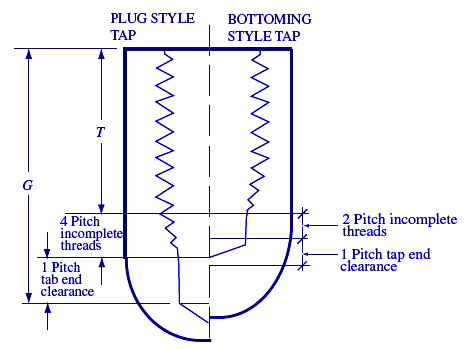
(1) The minimum drilling depths allow for
a) countersinking the drilled hole to prevent a feather edge at the start of the
tapped hole.
b) 0.75 to 1.5 pitch of insert set-down to allow for maximum production tolerance.
c) Dimensions are shown for both plug and bottoming taps. Plug taps 8 mm
and smaller have a male center, and the drilled hole depth dimensions allow for
this length (one-half of the diameter of the bolt).Calculation of minimum drilling
depth dimension G is as follows:
- Plug taps 8 mm and smaller, G = insert nominal length + 0.5 × nominal bolt diameter + 4 pitchs for tap chamfer + 1 pitch for tap end clearance + 1 pitch allowance for countersink and maximum insert set-down.
- Plug taps larger than 8 mm, G = insert nominal length + 4 pitchs for tap chamfer + 1 pitch for tap end clearance + 1 pitch allowance for countersink and maximum insert set-down.
- Bottoming taps, G = insert nominal length + 2 pitchs for tap chamfer + 1 pitch for tap end clearance + 1 pitch allowance for countersink and maximum insert set-down.
countersink
holes with insert set-down of 1.5 pitch maximum (See Fig. 1.).
The dimension T = insert nominal length + 1 pitch.
(3) Thread diameters are calculated as follows:
- Pitch diameter, min. Pitch diameter, min. of nominal thread 2 · Hmax
- Pitch diameter, max. Pitch diameter, max. of nominal thread 2 · Hmin
- Major diameter, min. Pitch diameter min. 0.649519 · P
- Minor diameter, min. Pitch diameter min. 0.433013 · P
- Minor diameter, max. Minor diameter min. tolerance
where Hmax and Hmin and tolerance is selected from the appropriate data provided in ASME B1.13M with basic major diameter equal to the minimum major diameter of the STI thread.
Related
- Metric Helical Helicoil threaded insert manufacturing installation specifications
- Metric External (Fasteners) Thread Designations Sizes M0.25 - M1.4
- Metric External (Fasteners) Thread Designations Sizes M1.6 - M18
- Metric External (Fasteners) Thread and Fastener Sizes M20 - M55
- Metric External (Fasteners) Thread and Fastener Sizes M56 - M78
- Metric External (Fasteners) Thread and Fastener Sizes M80 - M100
- Metric External (Fasteners) Thread and Fastener Sizes M105 - M135
- Metric External (Fasteners) Thread and Fastener Sizes M140 - M175
- Metric External (Fasteners) Thread and Fastener Sizes M180 - M255
- Metric External (Fasteners) Thread and Fastener Sizes M260 - M1060
- Metric Internal (Fasteners) Thread Designations Sizes M0.25 - M8
- Metric Internal (Fasteners) Thread Designations Sizes M9 - M24
- Metric Internal (Fasteners) Thread Designations Sizes M24 - M50
- Metric Internal (Fasteners) Thread Designations Sizes M52 - M72
- Metric Internal (Fasteners) Thread Designations Sizes M75 - M120
- Metric Internal (Fasteners) Thread Designations Sizes M125 - M180
- Metric Internal (Fasteners) Thread Designations Sizes M185 - M230
- Metric Internal (Fasteners) Thread Designations Sizes M235 - M600
