Related Resources: hardware
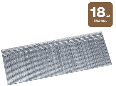
Brad Nails Standard Size and Length
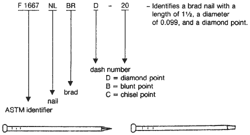
Brad Nails, Type I, Style 1 per ASTM F 1667
Steel wire, brad head, diamond point, round smooth shank, bright finish. When specified, brads shall have a modified brad head with a blunt or chiseled point for use with mechanical drivers.
All sizes given in inches
Where:
S = trade designation (reference in penny weight),
L = length, in.,
D = shank diameter, in.,
No. / lb = approximate count per pound
Notes:
- The lengths, L, of nails and spikes with flat heads or parallel shoulders under the head shall be measured from under the head or shoulder to the tip of the point.
- The diameter, D, of smooth shank nails and spikes shall be measured away from the gripper marks. The diameter, D, of formed or deformed shanks shall be measured before deformation, or, if specified, the thread crest diameter after deformation, or both. All diameter dimensions shall be taken prior to the application of or after the removal of any coatings or finish.
- Shank diameter tolerances shall be ±.002 in. for diameters smaller than 0.076 in. and ±.004 in. for diameters 0.076 in. and larger.
- Length tolerances shall be ±1⁄32in. for lengths up to and including 1 in.; ±1⁄16 in. for lengths over 1 in., up to and including 21⁄2in.; ±3⁄32 for lengths over 21⁄2 in., up to and including 7 in.; and ±1⁄8 in. for all lengths over 7 in.


Source
ASTM F 1667
and other ASTM Standards:
A 153 Specification for Zinc Coating (Hot-Dip) on Iron and
Steel Hardware
A 510 Specification for General Requirements for Wire
Rods and Coarse Round Wire, Carbon Steel3
A 641 Specification for Zinc-Coated (Galvanized) Carbon
Steel Wire
B 695 Specification for Coatings of Zinc Mechanically
Deposited on Iron and Steel
F 547 Terminology of Nails for Use with Wood and Wood-
Base Materials
F 592 Terminology of Collated and Cohered Fasteners and
Their Application Tools
F 680 Test Methods for Nails
F 1575 Test Method for Bending Yield Moment of Nails
Related
- Standard Nail Size Table Chart and Nail Terms
- Wood Nail Pullout Withdraw Resistance Force Formulae and Calculator
- Common Nails Required for Rafter Ceiling Joist Heel Joint Connections
- Lag Screw Wood Withdrawal Force Formula and Calculator per. AWC-NDS
- Lag Screws in Wood Pullout Withdraw Resistance Force Formulae and Calculator . Lag screws are commonly used because of their convenience, particularly where it would be difficult to fasten a bolt or where a nut on the surface would be objectionable.
- Wood Screw Pullout Withdraw Resistance Force Formulae and Calculator
- Wood Glue Joint Bevel Surfaces Strength Formulae and Calculator Wood Adhesive tapered angle joint equations for stress in tension, stress in shear, tensile stress in brazed joint.
- Bolts and Screws Design Rules for Wood Installation, Allowable Loads and Stress in Wood with Fastener , Screw Spacing in Wood , Allowable Loads and Stress in Wood with Fastener - Wood Post-1991 Equations and Calculator
- Wood Shear Stress Design Formulas and Calculator
- Length of Screw Thread Engagement per. ISO 965-1 Calculator , Formula and Table Length of engagement of mating threads is selected to utilize full tensile strength of a bolt prior to shearing and nut threads.
- Cold Form Tapping Theoretical Hole Size Equation and Calculator
- Thread Shear Area for External and Internal Formulas and Calculator per. ASME B1.1
- UN Internal Screw Threads Formulas and Calculator per. ASME B1.1
- Pitch Diameter of Threads Calculator and Formula
- Inch Size UN External Screw Threads Formulas and Calculator per. ASME B1.1