Figured out #1 and #2. Would still be interested in the answer to #3. Maybe the capabilities chart is based on Engineers Edge staff experience, not on a written reference ...
Hello,
There is a chart for mechanical location tolerance capabilities at www.engineersedge.com/manufacturing/drill-mechanical-tolerances.htm. Three questions in decreasing order of importance:
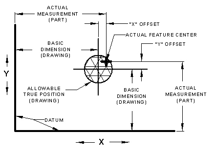
1. Regarding the minimum recommended position tolerances, are they true position diameters or else coordinate offsets (pictured below and at www.engineersedge.com/calculators/true_position_pop.htm
2. I don't understand the equation xxx = Positional Tolerance x .356. Can someone plug in numbers for an example?
3. What is the source of this chart? It appears that only the top chart (hole diameter tolerances) comes from the referenced AND10387 standard.

Last edited by Kelly_Bramble; 11-12-2016 at 08:47 AM.
Figured out #1 and #2. Would still be interested in the answer to #3. Maybe the capabilities chart is based on Engineers Edge staff experience, not on a written reference ...
They are limit tolerances +/- tol.
This is simplified math for converting a cylindrical or round tolerance boundary to a square tolerance boundary.
For example - draw a tolerance circle (position tolerance) = .014. Then draw the largest perfect square that can fit into the circle. That square should be equal to .010 side to side or .014 corner to corner. The square tolerance zone represents a +/- .005 tolerance specification. Therefore, .014 x .356 = .004984 or .005. Or in reverse, .005 / .356 = .01404494 or .014.
The tolerance chart and equations require some knowledge of GD&T tolerance, limit tolerances and the conversion between them.
My research, experience and other great DFM/DFMA and mechanical tolerance data can be found in my Book "Engineering Design Manufacturing" http://engineersedge.com/catalog/pro...roducts_id/28/
Tell me and I forget. Teach me and I remember. Involve me and I learn.
Thank you for the chart's reference.