Related Resources: Analysis Engineering and Science
Power Transmission Shaft under Fatigue Loading Using ASME Code
Beam Deflection and Stress Calculators Formulas & Structural Analysis
Design of a Power Transmission Shaft under Fatigue Loading Using ASME Code
Based on American Society of Mechanical Engineers (ASME) Standard B106.1M:1985
Abstract
Power transmission shafting is a vital element of all rotating machinery. A complete shaft design involves many iterative phases and fundamental to this is the determination of preliminary dimensions of the shaft. This paper presents a comprehensive fatigue analysis approach of determining the initial dimensions of a power transmission shaft under fatigue loading based on American Society of Mechanical Engineers (ASME) Standard B106.1M:1985. A countershaft running at a constant speed is designed using this approach. Stress analysis at potential critical locations are conducted to determine the shaft sizes. The sizes from these locations are then used to estimate the sizes at low stress locations. Adjacent sizes are blended using the largest size. To help visualize, a CAD model of the preliminary designed countershaft is provided.

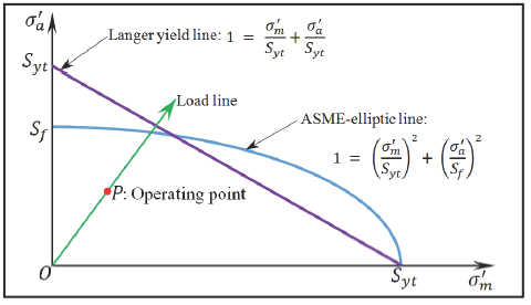
Reference Figure 7
Design region and load line for ASME-elliptic and Langer yield theories, for the tensile region (σm ≥ 0)
Introduction:
One of the first fundamental facts of which human beings become aware is that nothing lasts forever. Life may come to a sudden end or last longer, but still for only a finite period (Vassilopoulos, 2010). As the industrial arena grows more sophisticated, it seems as though operations are confronting fewer and fewer broken machine shafts. When shafts do break, however, there are almost always as many theories regarding the suspected culprits as there are people involved (EP, 2018). Whether related to motors, pumps or any other types of industrial machinery, shaft failure analysis is frequently misunderstood, often being perceived as difficult and expensive. For most machine shafts, however, analysis should be relatively straightforward. That’s because the failure typically provides strong clues to the type and magnitude of forces on the shaft and the direction they acted in: The failed parts will tell exactly what happened (EP, 2018).
Free Membership Minimum Required
Open (Pop up): Design of a Power Transmission Shaft per. (ASME) Standard B106.1M
Reference
Stephen K. Armah
Department of Mechanical Engineering,
North Carolina A&T State University, Greensboro, NC, USA
Related
- Rotating Shaft Design Combined Loading Formulae and Calculator
- ASME Shaft Design Allowable Stress and Diameter equations and calculators
- Shaft Diameter Maximum Material Condition MMC vs Feature Size Tolerance Chart Tool Calculator
- Shaft (Arbor) Keyway Dimension Size Data - ANSI/ASME B94.19-1997
- Shaft Reliability and Design Formulae and Calculator
- Torsional Rigidity Solid Shaft vs Hollow Shaft Formulas and Calculator
- Solid Shaft Equivalent of Hollow Shaft Strength Formula and Calculator
- Combined Loading on Circular Beam or Shaft in Direct Compression Stress Equation and Deflection Calculator
- Combined Loading on Rectangular Beam or Shaft in Direct Compression Stress Equation and Deflection Calculator
- Shaft Torsional Deflection and Rigidity Formulas and Calculator
- Torque Applied Deformation and Stress of a Shaft with Keyway Equations and Calculator
- Torque Applied Deformation and Stress of a Shaft with Two Keyway's Equations and Calculator
- Torque Applied Deformation and Stress of a Shaft with Four Keyway's Equations and Calculator
- Torque Applied Deformation and Stress of a Shaft with One Spline Equations and Calculator
- Torque Applied Deformation and Stress of a Pinned Shaft Equations and Calculator
- Stress Concentration Cylinder feature with Axial Loading